Blog
Understanding Antennas and EME Exclusion Zones: Ensuring Safety and Compliance
As the demand for wireless communication grows, so does the need for understanding the safety measures associated with antenna installations. One critical aspect is the establishment of Electromagnetic Energy (EME) exclusion zones. These zones ensure that exposure to radiofrequency (RF) fields is within safe limits, protecting both the public and workers. In this blog post, we’ll explore what EME exclusion zones are, why they are important, and how to ensure compliance with safety standards.
What are EME Exclusion Zones? EME exclusion zones are areas around an antenna where the levels of RF exposure exceed the recommended safety limits. These zones are established to prevent human exposure to harmful electromagnetic fields. The size and shape of an exclusion zone depend on various factors, including the type of antenna, frequency, power output, and installation height.
Importance of EME Exclusion Zones:
- Safety: Ensuring that EME exclusion zones are properly established helps protect individuals from excessive RF exposure, reducing the risk of health issues.
- Compliance: Regulatory bodies, such as the Australian Radiation Protection and Nuclear Safety Agency (ARPANSA), set guidelines and standards for RF exposure. Compliance with these standards is essential for legal and operational reasons.
- Public Confidence: By adhering to safety guidelines and maintaining exclusion zones, telecom operators can build public trust and demonstrate their commitment to safety.
Guidelines for Establishing EME Exclusion Zones:
- Site Assessment: Conduct a thorough assessment of the site to identify potential sources of RF exposure and determine the appropriate exclusion zones.
- Calculations and Modeling: Use specialized software and tools to calculate the size and shape of the exclusion zones based on the antenna’s specifications and operating conditions.
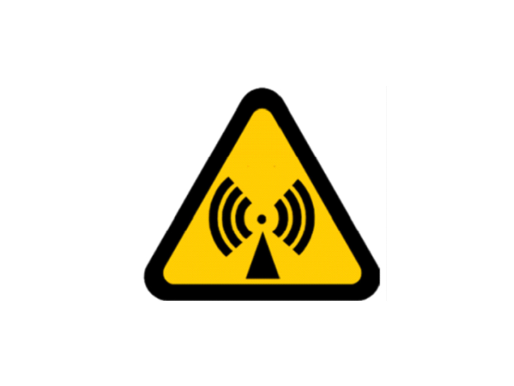
- Signage and Barriers: Clearly mark the exclusion zones with signs and physical barriers to prevent unauthorized access.
- Regular Monitoring: Continuously monitor RF exposure levels to ensure that they remain within safe limits and adjust exclusion zones as needed.
Compliance and Regulation:
- ARPANSA Guidelines: In Australia, ARPANSA provides comprehensive guidelines for managing RF exposure and establishing exclusion zones. Adhering to these guidelines is crucial for compliance and safety.
- Training and Awareness: Ensure that all personnel involved in antenna installation and maintenance are trained on EME safety and understand the importance of exclusion zones.
Conclusion: Understanding and implementing EME exclusion zones is vital for the safe installation and operation of antennas in the telecom industry. By following regulatory guidelines and best practices, you can protect individuals from harmful RF exposure and ensure compliance with safety standards.


