Blog
How to Create Site Elevation Drawings for the Telecom Industry: A Step-by-Step Guide
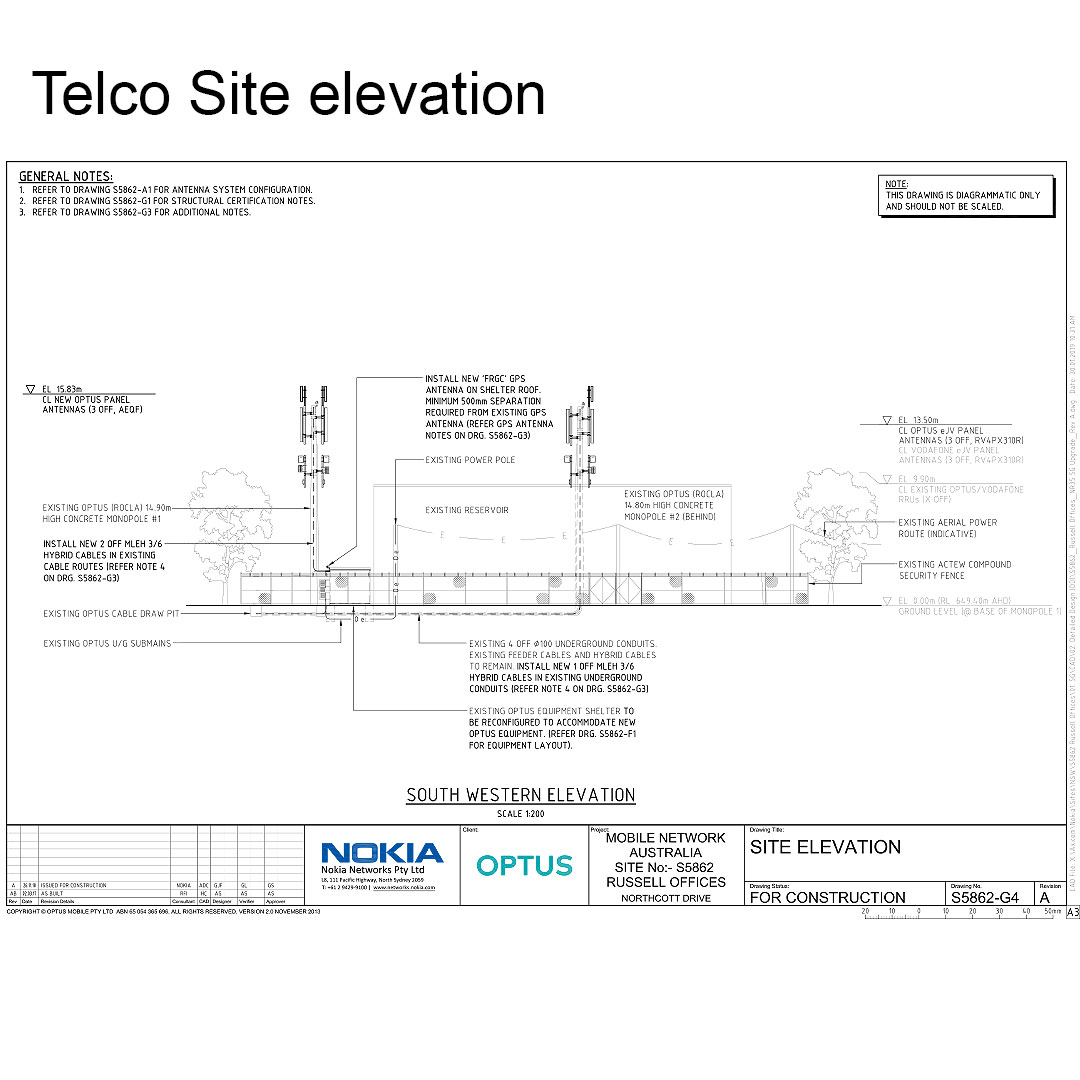
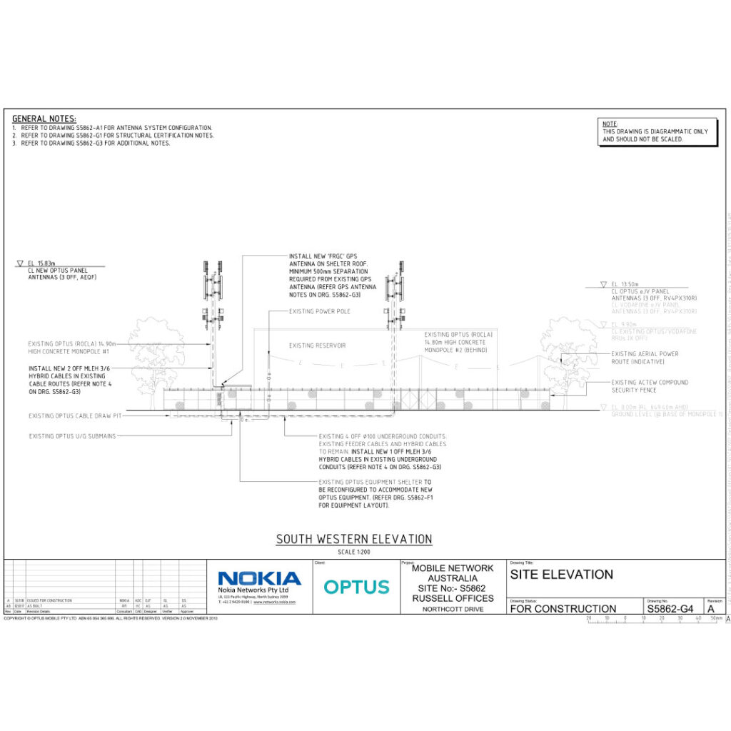
Site elevation drawings are critical in the telecom industry for planning and executing infrastructure projects. These drawings provide a detailed view of the vertical aspects of a site, helping engineers and architects understand the terrain and design accordingly. In this guide, we’ll provide step-by-step instructions for creating site elevation drawings, along with best practices and compliance tips.
What are Site Elevation Drawings?
Definition: Site elevation drawings are technical illustrations that depict the vertical dimensions and terrain features of a telecom site. These drawings are used to plan the placement of towers, antennas, and other structures, ensuring they fit within the landscape.
Purpose: The primary purpose of site elevation drawings is to provide a clear understanding of the site’s topography, helping to plan for potential challenges and ensure the optimal placement of equipment.
Key Components of Site Elevation Drawings
- Vertical Dimensions:
- Height Measurements: Accurately measure and depict the height of various structures and natural features.
- Elevation Points: Mark key elevation points to illustrate changes in terrain.
- Terrain Features:
- Slopes and Gradients: Clearly indicate slopes and gradients to plan for construction and placement of equipment.
- Natural Obstacles: Identify trees, rocks, and other natural obstacles that may impact construction.
- Structural Placement:
- Towers and Antennas: Show the planned location and height of towers, antennas, and other telecom equipment.
- Access Points: Include access points for maintenance and emergency services.
- Regulatory Compliance:
- Safety Zones: Ensure safety zones are clearly marked and compliant with regulations.
- Permits and Approvals: Note any required permits and approvals in the drawing.
Step-by-Step Instructions for Creating Site Elevation Drawings
- Conduct a Site Survey:
- Perform a detailed site survey to gather accurate measurements and data.
- Gather Tools and Resources:
- Use advanced tools like CAD software to create precise and detailed drawings.
- Draw the Base Map:
- Begin with a base map of the site, including all existing structures and terrain features.
- Add Elevation Points:
- Mark key elevation points and indicate changes in terrain.
- Draw Structures and Equipment:
- Sketch the planned placement of towers, antennas, and other equipment.
- Include Safety Zones:
- Clearly mark safety zones and ensure they comply with regulatory requirements.
- Review and Revise:
- Regularly review and revise the drawing to incorporate any changes or improvements.
Best Practices for Site Elevation Drawings
- Use Accurate Data:
- Ensure all measurements and data are accurate to avoid errors in the drawing.
- Collaborate with Experts:
- Work with engineers, architects, and regulatory bodies to ensure the drawing meets all requirements.
- Stay Updated:
- Keep up with the latest industry standards and regulations to ensure compliance.
- Document Everything:
- Maintain detailed documentation of the drawing process and any changes made.
Conclusion: Creating accurate site elevation drawings is essential for successful telecom projects. By following the steps and best practices outlined in this guide, you can ensure your drawings are precise, compliant, and efficient.